Monday, May 23, 2011

Tracking Shots with GEF3D

One of the most important things for 3D user interfaces are good navigation tools. So far, GEF3D comes with a nice first person like camera tool. You can fly around in the 3D scene and orbit around figures. If you have watched previous GEF3D videos, you may have noticed how we fiddled to nicely position figures in front of the camera. This is more or less ok for editing smaller diagrams, but in the long run it's annoying. In order to improve navigation, we needed a basic technique for tracking shots (see bug 30019 ). I have now added a basic API for tracking shots, together with some predefined shots for moving the camera in front of figures, as demonstrated in the following video.


These tracking shots are now (as of GEF3D revision 578) available, and the default camera tool provides the following (old and new) navigation features:
  • move camera around with keys (up, down, etc.), mouse (grab scene and drag it around) or mouse wheel or touch pad with two fingers (zoom in / out)
  • orbit around figures by holding down a modifier key and clicking on a figure to be the center of the orbit
  • new: double click on a figure to start a tracking shot, ending in front of the figure. The double clicked figure will then be shown in the center of the 3D scene, much as if opened in a 2D editor.
  • new: double click on background, to start a tracking shot to a predefined position. The default camera tool defines three positions, in order to look at the 3D scene from the front, from the side (hold modifier), or from the top (hold shift and modifier).

Actually, the idea of tracking shots in GEF3D is not that new. It had been prototypically implemented in a master thesis 2008 (see A. Bauer: Visualisierung von Suchtreffern und Clustern in 3D-Diagrammeditoren.) -- however the new moves are much nicer ;-) I'm looking forward to re-implementing the basic feature of this thesis again using the new tracking shot API: We combined EMF search with GEF3D, in order to automatically move the camera to search hits visualized in the 3D scene. And there are much more applications for tracking shots, such as following connections, visualizing timelines, switch between "sub-scenarios" in the 3D scene, etc. Stay tuned!

Jens

Friday, May 13, 2011

Interactively rotate and move figures in 3D space

Although GEF3D provides full 3D capabilities for placing and rotating figures, it was not possible to interactively place figures everywhere in 3D space. GEF3D adapts moving and resizing of figures as provided by GEF, by enabling moving and resizing of figures on so called virtual planes (which are unbounded surfaces). Since surfaces are always 2D planes, this is similar to moving figures in a 2D editor (in which the surface is always the screen surface). As of revision 576 (we are still working on a nightly build system, until then you have to get GEF3D from the code repository), it is possible to interactively move figures in 3D space. In the movie below, you will see how some planes are interactively moved and placed in 3D space. The editor is part of the GEF3D examples. It consists of simple (2D GEF) editors for graphs, that is labeled nodes connected with edges. Several graphs, each one drawn on its own diagram surface, are combined into a GEF3D multi editor. You will find this example called "Multiple Graphs in Dia2D Mode Sample" in the example package (org.eclipse.gef3d.examples.graph).

This closes bug 300321 and it also demonstrates a lot of nice features of GEF3D which are not that obvious. In the following, I will highlight some interesting aspects, using some snapshots taken from the movie.

Fig. 1: Virtual Plane
Figure 1 shows how 2D figures can be moved around just like moving figures with GEF. GEF3D provides a concept called "virtual planes", that is, a figure is moved parallel to a (virtually extended) surface of a 3D figure, which usually is the surface of the diagram. This always worked for 2D  figures. (For people not that much involved in GEF3D: a 2D figure actually is an original GEF or Draw2D figure! It's code is not modified at all!)

Fig. 2: 2D breaks free!
As shown in Figure 2, 2D figures are not necessarily bound to the actual surface of a 3D figure. Instead, 2D figures are rendered as real 3D content, which does improve quality and performance (Kristian is a real 3D wizard making this possible), but also removes restrictions on how 2D content is drawn in 3D.

Fig. 3: Move 3D figure on virtual plane
Now, 3D figures can be moved like that as well. A 3D figure, which is not placed onto a figure with a surface, such as the digram figure itself, can then simply be moved parallel to its own surface. This is illustrated in Figure 3.

Fig. 4: Interactively rotate 3D figure
One of the most interesting features of GEF3D is the full support of rotation. In the current version, 3D figures can be interactively rotated by holding down a modifier key (command key for on OS X, alt key for Windows and Linux). Instead of moving the figure, it is then rotated around its own x- and y axis. Figure 4 shows the feedback figure, which exactly shows the rotation.
Fig. 5: Connection anchors are placed correctly
One of the trickiest things with rotations is the correct handling of connection and connection anchors. Figure 5 shows that the connection between an element of the one diagram is still correctly connected with an element of another diagram, although the first diagram is rotated. This works with all arbitrarily rotated figures. Since 2D content is rendered using OpenGL as well, we also have no problems with image quality or whatever. So, if you need fully supported rotation capabilities for a 2D editor (in which the figures are to be rotated around the z-axis), GEF3D may be interesting for you as well (all you need to do is to restrict the camera in order to emulate a 2D editor).

Fig. 6: Move along normal vector
Holding down the modifier and shift will cause the figure to be moved orthogonally to the virtual plane, that is along its own z-axis (or normal vector). This is shown in Figure 6.

Fig. 7: Resize 3D figure
This enables one to arbitrarily place 3D figures in the 3D space. It is also possible to resize 3D figures, however at the moment I only have implemented the resizing itself. Thus, only resizing along the x- and y-axis are supported (as shown in Figure 7), because only handles for x- and y-resizing are provided yet.

While modifier keys may work in some cases, it is only a temporary hack. In the long run, we have planned to add 3D handles. We are thinking about adding handles for x-, y-, and z-axis rotation, z-axis movement, and resizing the depth of a figure. This will also remove conflicts with applications using the modifier keys for different kind of actions.

Jens

Sunday, February 27, 2011

Welcome Miles!

I'm happy to welcome Miles Parker as a new GEF3D committer. Miles is the master of agents, that is he is project lead for the Eclipse AMP, the Agent Modeling Platform. In this context, he is using GEF3D for quite some time to create impressive 3D visualizations of agent models. He also has some experiences with fighting continuous integration build systems---and winning these fights. He will help the GEF3D team to set up a build system with Buckminster and Hudson. So we will be able to create nightly builds and, in the long run, a first release of GEF3D.

Monday, September 13, 2010

Do you want 3D in Eclipse?

Unfortunately, we were informed that the JOGL library has failed to get IP approved just like LWJGL due to severe licensing problems (see CQ2817 and GQ2840 for further details; IPZilla account needed). To summarize, LWJGL cannot be approved as it contains non BSD code or code with unknown license or provenance and JOGL cannot be approved as “we have been unable to locate an individual within Sun/Oracle to help us with JOGL”, as Janet Campbell wrote when closing the CQ. In this context we'd like to thank Janet and Barb for all their hard work!

What this means for Eclipse is that, even though it is technically possible to use 3D / OpenGL within Eclipse, there is no way to create self-contained Eclipse plugins that require OpenGL. Such plugins would always have to rely on external update sites, which complicates the installation process. Such update sites also depend on third party support and may or may not be available in future releases. For GEF3D, this is really bad news, but it also is a problem for all other 3D related projects.

The only option appears to be to create a new Eclipse project for OpenGL bindings. Some work has been done in the SWT project itself, but the code has since been abandoned. Unfortunately, writing OpenGL bindings for Java is not a simple job due to inconsistencies and driver incompatibilities. Jens wrote GEF3D in the context of his Ph.D. thesis, and we both were paid by the FernUniversität in Hagen. Additionally, we spent a lot of our spare time on GEF3D. We both are still interested in GEF3D, but unfortunately our current work is not really 3D related. That is, we both are no longer paid for maintaining GEF3D. This would be OK to a certain degree, but frankly none of us is keen on writing a new OpenGL wrapper library on our own without any salary.

So, we'd like to know whether we are alone in our effort to bring 3D to Eclipse: Do you want 3D (i.e. OpenGL) in Eclipse? And if you do, what are your thoughts on this situation? As this is not a simple yes/no question, please leave us a comment.

Jens and Kristian

Technical Note: OpenGL is required for almost all 3D applications, and high-level libraries such as the JMonkeyEngine or Aviatrix3D use OpenGL (i.e. LWJGL or JOGL) under the hood. Technically, OpenGL can be easily used in SWT applications thanks to the GLCanvas class. However, a Java wrapper library is needed for calling OpenGL functions. As far as we know, only two such libraries are available: LWJGL and JOGL. At http://www.eclipse.org/swt/opengl/, gljava is listed as well, however, this project is no longer maintained. The same is true for the org.eclipse.opengl bindings. There exists a plugin for JOGL, and another for LWJGL. The plugin for LWJGL has been written in the context of GEF3D and has been maintained by the LWJGL team for quite a while (they have changed their build system, so the LWJGL plugin is no longer maintained at the moment, however the update site is still available).

Wednesday, May 5, 2010

Multi editor 3D and property sheet pages

Besides enabling 3D editors, IMHO one of the most interesting features of GEF3D is to combine existing editors. I already blogged about that feature one year ago, and since then GEF3D has been improved very much.

The rendering quality is now as good as in 2D, so it really makes sense to think about supporting 3D when creating new editors. However, the nice thing about GEF3D is, that you do not have to write new editors from scratch, instead, you can reuse existing editors. And, these reused editors can not only adapted in order to support 3D -- we call this "3D-fied" -- but they can also be adapted in order to be combined. For that, all you have to do is to let them implement a small interface INestableEditor. It is very simple, the GEF3D examples include 3D-fied and nestable versions of the UML2 Tools editors and the Ecore Tools editors.

When combining editors, a lot of new problems arise. One of these problems is how to create new edit parts. Every nested editor comes with its own factory -- but which one to use in case of newly created elements? This problem is solved in GEF3D for quite some time now (by the multi factory pattern). I only recently became aware of another "combination" problem: the property sheet page. Every editor provides its own page, created almost hidden via getAdapter(). Now -- what page do you want to use in case of a multi editor? The answer is simple: The right page, depending on the selected element. And this is what I've added to GEF3D: Depending on the currently selected element, the page provided by the nested editor responsible for that element should be used. The latest (SVN) revision of GEF3D provides a new page, called MultiEditorPropertySheetPage, which nests all the pages provided by the nested editors. Depending on the currently selected element, the appropriate page is shown, as you can see in the screenshots. As many things in GEF3D, this feature is almost transparent to the programmer.

use case selected, property page provided by nested UML editor


ecore class selected, property page provided by nested Ecore editor


The screenshots show an UML use case diagram (visualized with 3D-fied UML tools) and an ecore diagram (visualized with 3D-fied Ecore tools). The 3D-fied editors and the multi editor combining them are examples of GEF3D (that is, you will find everything in the SVN).

In many cases models are visualized as diagrams, and with GEF3D and its multi editor feature you will be able to easily display all your diagrams in a single 3D scene -- with things you aren't able to visualize in 2D editors, such as inter-model connections (traces, markers, mappings, or other kind of weaving models). Some products use the term "modeling IDE" -- think about the "I" in IDE and what GEF3D does with your models ;-)

BTW: The very same concept used for implementing property sheet pages may be implemented for the Outlook View as well -- volunteers wanted :-D

Jens

Tuesday, February 2, 2010

Improving Visual Rendering Quality

As Jens mentioned in his recent blog post, parts of the Draw3D renderer have been rewritten in the past weeks. The initial motivation was to improve the visual rendering quality of 2D content (embedded GEF editors) and text, but during development it turned out that a lot of optimization would be necessary to keep the performance at acceptable levels. Eventually, I rewrote the renderer to take advantage of some advanced OpenGL features and now the performance is a lot better than it ever was.

In this blog post I will briefly explain how the 2D rendering system was redesigned over the course of GEF3D's existence and how it was possible to achieve both a gain in the visual quality and the rendering performance at the same time.

First, let me introduce the initial 2D rendering system that Jens designed before I came on board. GEF uses an instance of the abstract class Graphics to draw all figures. Actually, figures draw themselves using their paint method whose only parameter is an instance of Graphics (this is defined in the IFigure interface). The Graphics class provides a lot of methods to draw graphical primitives like lines, rectangles, polygons and so forth, as well as methods to manage the state of a graphics object. Usually, GEF passes an instance of SWTGraphics to the root of the figure subtree that needs redrawing. SWTGraphics uses a graphics context to draw graphical primitives, and the graphics context usually draws directly onto some graphics resource like an image or a canvas.

So what Jens did when he wanted to allow 2D content in GEF3D was that he simply passed an instance of SWTGraphics to the 2D figures that rendered into an image in memory. This image was then transferred to the graphics card and used as a texture. This system was very simple and required hardly any additional coding at all. The problem with this approach however is that whenever the 2D content needed redrawing (after some model change for example), the entire image had to be redrawn and uploaded to the graphics card again, which is a very costly process. First, the image has to be converted into a ByteBuffer and that buffer must then be uploaded from system to video memory through the bus. For normal-sized image, this can take up to 500ms.

To alleviate this problem, I wrote another Graphics subclass that uses OpenGL to render the 2D primitives directly into a texture image in video memory. This eliminates the uploading step and thus improved performance considerably, especially the delay after any model change when the texture image had to be uploaded into video memory. But it did not help with the second major problem: It still used textures. The problem with using textures to display 2D content in 3D is that while the texture image may look sharp and very good by itself, it gets blurry and distorted when it is projected into 3D space due to all the filtering that has to take place. Especially images that contain text become very hard to read in this approach, as you can see in this screenshot:

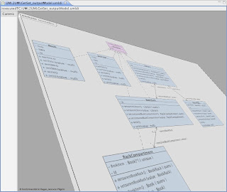
TopCased editor, 3D version with 2D texture
Another approach to rendering 2D content in 3D is not to use textures at all, but to render all 2D primitives directly into 3D space in every frame (so far, only the texture had to be redrawn only after a model change occurred). This eliminates all problems related to texture filtering and blurring once and for all. Combined with vector fonts (to be described in another blog post), direct rendering results in the best possible visual quality. The problem is that everything needs to be rendered in every frame all the time. I quickly discovered that simply sending all geometry data to OpenGL in every frame (this is also called OpenGL immediate mode) would kill performance - even in small diagrams, navigation became sluggish.

Essentially, the FPS in GEF3D are limited not by the triangle throughput of the video card (how many triangles can be rendered per second?), but by the bus speed (how much data can we send to the video card in a second?). If you send all your geometry, color and texture data to the video card on every frame, your performance will be very bad because sending large amounts of data to the video card is very expensive. The more data you can store permanently in video memory, the better your performance will be (until you get limited by triangle throughput). So we had to find a way to store as much data as possible in video memory and just execute simple drawing instructions on every frame.

Of course, OpenGL provides several ways to do this. The first and oldest approach is to use display lists, which is basically a way to tell OpenGL to compile a number of instructions and data into a function that resides in video memory. It's like a stored procedure that we can call every time we need some stuff rendered. The problem with display lists is that they are fine for small stuff like rendering a cube or something. 2D diagrams however consist of large amounts of arbitrary geometry, which cannot be compiled into display lists at all. So this approach was not useful for us.

The best way to store geometry data in video memory is called a vertex buffer object (VBO) in OpenGL. Essentially, a VBO is one (or more) buffer that contains vertices (and other data like colors and texture coordinates). These buffers only need to be uploaded into video memory once (or when some geometry changes) and can then be drawn by issuing as little as five commands in every frame. We decided to adopt this approach and try it for our 2D diagrams by storing the 2D primitives in vertex buffers in video memory. Rendering a 2D diagram would then be very fast and simple, because hardly any data must be sent to the video card per frame. This is how the pros do it, so it should work for us too!

In theory, that is correct. But in practice, it is very hard to actually create a vertex buffer out of the 2D content of a 2D diagram. Since a vertex buffer can only contain a series of graphical primitives (triangles, quadrilaterals, lines) of the same type and the primitives that make up the 2D diagram are drawn in random order, the primitives need to be sorted properly so that we can create large vertex buffers from them. Unfortunately, the primitives cannot simply be sorted by their type and then converted into vertex buffers because there are dependencies between such primitives that intersect. To cut a long story short, I had to think of a way to sort primitives into disjunct sets. Each set contains only primitives of the same type and each set should be maximal so that you end up with a small number of large buffers because that's how you achieve maximum performance.

The end result is impressive: We used to have performance problems with diagrams that contain more than 2000 2D nodes, and now we can display 4000 2D nodes at 120 FPS, and all that with much better visual quality. To get an idea of how much better the quality of the 2D diagrams is in this version, check out the following screenshot:

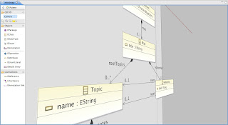
Ecore editor 3D with high quality 2D content
Kristian

Friday, January 22, 2010

2.5D breaks free.. and future plans

I assume Kristian will tell you more in a future post, but I simply couldn't wait to show you this picture:

GEF3D ecore editor (rev. 436)

It shows a screenshot of the 3D-fied version of the ecore tools editor, which is part of the GEF3D examples. Compare this image (GEF3D rev. 436) with the following one, taken using an elder version (rev. 413 ) of GEF3D showing the very same diagram:

GEF3D ecore editor, rev. 413

Do you see the difference? Yeah! 2D figures are no longer bound to their diagram plane! In other words: 2.5D breaks free! (If you don't know the term 2.5D, read our tutorial article about GEF3D available at Jaxenter.com!) Besides, the display quality of 2D content has improved since it is now rendered as vector graphics and no longer as a smudgy texture projected onto a plane. Usually, increased display quality leads to decreased speed, but not in this case! Actually, GEF3D is no longer a limiting factor when displaying large diagrams -- it's GEF (or GMF). The texture based version of GEF3D had a problem with diagrams containing about 5.000 (2D) nodes. The new version runs smoothly even with this much nodes! However, you may get a memory problem when opening such large diagrams (due to GEF/GMF), but if you can open it, the camera can be moved smoothly! Great work, Kristian! He has become a real 3D programming pro, and I'm absolutely impressed about how he improved GEF3D in the last weeks. Stay tuned to his post about this new technique!

At the moment, Kristian is working on also replacing the texture based font rendering with vector fonts, which will dramatically improve the overall quality of the rendered images. Besides, the GEF3D team has set up a todo list, summarizing bugs with new features (to be implemented in the near, not so near and far future):


The most important tasks are to add support for full 3D editing, e.g. moving and resizing figures in z-direction and rotation, implement advanced animation support and, depending on that, camera tracks. If you have ideas, please post an article on the GEF3D newsgroup!

I certainly have some bias, but with vector based 2D content (and fonts) and camera tracks (e.g., for positioning a diagram in a kind of 2D view), the quality and comfort of editing a 2.5D diagram will become the same as editing it with pure GEF in 2D. But with GEF3D, you can work with multiple diagrams much more comfortable: If you have to edit multiple diagrams with inter-model connections, you will be able to simply navigate to another diagram (and back again). And you can actually see the inter-model connections (for an example read Kristian's post about his 3D GMF mapping editor). 2D is dead, long live 3D!

Well, ok, I have probably watched too much Avatar 3D ;-). But maybe you like the idea of cool 3D diagrams, too? Then join the GEF3D team, grab yourself a bug and see how much fun 3D programming with GEF3D could be! Yes, I know... there is no release of GEF3D available yet... I will do that as soon as possible, and I hope with the help of Miles Parker we will be able to set up a build system shortly. So long, use the project team set and check out GEF3D from the SVN repository, an installation tutorial can be found in the Wiki.

Last but not least, I'm happy to announce the third and (so far) last part of our GEF3D article series in the german Eclipse Magazin, 2.10. In this part, Kristian and I explain how to 3D-fy existing GMF editors.

Jens